


In today’s electronics equipment, total system dissipated power levels are increasing with every new design. Increases in power levels combined with the market expectation of reduced package sizes lead to heat problems that, if uncontrolled, can significantly shorten the life of the electronics. Although this “increased power – decreased size” scenario has been prevalent for many decades, the industry’s ability to make smaller electronic components mandates reduced size cooling components.
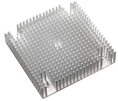 |
Figure 1. Cross-cut extrusions improve overall thermal performance in forced convection.Market demands have shifted attention to decreasing the volume and increasing thermal efficiency. For some electronics (typically uninterruptible power supplies and telecommunications systems) the market also demands reduced floor space and places severe limitations on acoustic noise. These limitations force designs toward more expensive heat removal techniques.
Total power level is not the only problem. Heat density, or Watts per square centimeter, at the semiconductor is a growing problem, too. This is the result of denser electronics and increased clock frequencies. High heat flux densities combined with high overall power levels are the main problems for thermal management. These thermal challenges can cause equipment failure even if the heat sink surface area and airflow are sized correctly.
Trends – Which Way Is Electronics Cooling Going?
Professor Avram Bar-Cohen from the University of Minnesota, known for its electronics cooling program, addresses the question “What does the future of thermal management hold for electronics?” in the following way: “I don’t know. One thing’s for sure; pretty soon plain old air-cooling isn’t going to cut it�!” [1]. This message sums up both the problem and the answer. The problem is that current air-cooling technologies are not adequate to deal with the demands of the electronics. The potential answer is also in this statement. Liquid-cooling offers many benefits including significantly higher heat removal capacity in reduced volume.
Air-Cooling in the Past
Air-cooling is the traditional method of cooling electronics. In the past, thermal design was only considered when lab tests failed or a component turned the PC board brown. As a heat transfer agent, air is a poor media with the following limitations:
- Low density and low specific heat, resulting in low heat carrying capacity
- Low thermal conductivity
However, due to its availability, low cost, ease of maintenance and “no problem if there’s a spill” characteristics, air-cooling is still the preferred choice.
Potential Enhancements in Air-Cooled Heat Sinks
Improved heat transfer is achieved in either of two ways:
- Increase the heat transfer coefficient, h.
- Add more exposed surface.
The heat transfer coefficient is a measurement of how effectively heat is removed from a surface. It is expressed in terms of Watts dissipated per square meter per degree C of temperature of rise above the cooling medium. Newton’s law of cooling states that heat dissipated is equal to the heat transfer coefficient (h) times area times the temperature rise between the heat sink and the cooling air or:
q = h � A � (Theat sink – Tair)(1)
A designer can control only “A”, the number of square centimeters of surface area of the fins, and “h”, the effectiveness of the heat removal from each square centimeter of surface. Both of these parameters are bounded by the limits of cost and marketability.
The heat transfer coefficient “h” can be increased by a number of methods:
- Increasing airflow velocity is most common. Increased airflow past the heat sink fins generally increases “h”. It also increases the mass flow rate, reducing the overall temperature of the exit air. Increasing air velocities past 8 to 10 m/s adds significantly to the backpressure and the acoustic noise.
- Crosscutting of flat fins into multiple short sections. This improves the heat transfer coefficient at the fin surface while slightly reducing the surface area exposed to the air stream. The drawback of this method is the resultant additional pressure drop. Typically, crosscutting is best employed where airflow is from an unpredictable direction (Figure 1). [2]
- Augmentation of fins is similar to cross cutting but adds a separate “twist” in the leading and trailing edge of a fin. This curvature of the metal into the air flow reduces the “h” by scrubbing the “dead’ air molecules away from the surface. Augmentation works best in air velocities of 3 m/s or higher (Figure 2). [3]
- Impingement (jet) cooling of heat sinks is achieved using a high-speed airflow directed at the fin tip toward the base. This cooling layout can increase heat removal but must be designed with an eye toward the system as a whole and tested in situ to be effective. [4]
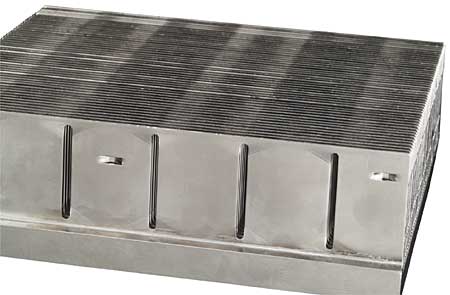 |
Figure 2. Augmented flat fins add air flow turbulence at increased cooling air velocities.Increased heat removal from any of these heat transfer enhancement schemes comes at the price of increased pressure drop. The heat sink, fan and system as a whole must be examined in conjugate analysis to determine if any of these techniques will produce lower overall thermal resistance than just increased surface area through increased numbers of thin, flat fins. A real limitation in this area is the ability to control contamination in the air stream. Closely spaced fins can cause clogging of the fins and a reduction in thermal performance.
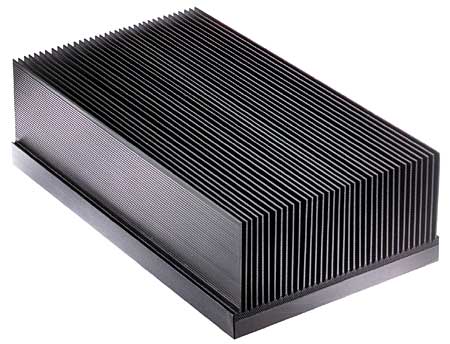 |
Figure 3. Bonded fin heat sink increases surface area 2X to 3X.
Higher Performance Fans
The technology of fans is also under scrutiny in the electronics cooling industry. If a fan with higher performance (significantly increased airflow at equivalent pressure drop) becomes available, many designs will be built around that fan. The difficulty in achieving this higher performance comes back to fan blade technology and motor design, as well as acoustic noise limitations. Future developments are expected in this market.
Increase Exposed Cooling Surface Area – Inexpensively
In convective heat transfer, the increase in heat removal is based on available cooling surface area. In many cases, the use of an increased number of tall, thin, flat fins will give better performance and less pressure drop than any modification of the fin shape. Based on airflow resistance, the flat fins maintain the lowest pressure drop and hence the greatest mass flow of air. A great deal of research is being put into low cost manufacturing methods of producing extended surfaces that incorporate more fins in smaller heat sink package sizes.
Aluminum Extrusions
Aluminum has many characteristics that make it an excellent heat sink material. It is easily shaped in fine detail with inexpensive tooling. But the height and number of fins, or extrusion ratio, limit surface area. The extrusion or aspect ratio of the fins is the limit that the extrusion tool can produce without failure. The aspect ratio of fin height to spacing has increased over the past decade from 6:1 up to as much as 15:1 depending on size and extrusion press operator. The objective of increasing those ratios is to create more fins in a smaller volume.
Serrations on extruded fins have for years been thought to increase surface area and hence heat transfer. In most cases they have no added thermal effect. Serrations can increase the heat removal rate but, as typically seen, are not tall enough to provide any increase in cooling over flat fins. [5]
Impact Extrusions
Three-dimensional extrusions formed by impact extrusion offer an alternative to the standard two-dimensional parts. Using the same high-conductivity alloy, impact extrusions are commonly seen as pin fin or elliptical fin parts. Extrusion or draw ratios exceed the capability of linear extrusions, offering an increase in the amount of surface area per unit volume.
Bonded Fin Heat Sinks
Bonded fin heat sinks use separate base and fins assembled to form a heat sink (Figure 3). For over a decade these parts have offered an alternative to the limitations of the extrusion process. Increases in cooling surface area of 200 to 300% allow significant decreases in heat sink volume. Many different assembly styles are available on the market. These are:
- Epoxy bonding of fins into a heat-spreading base
- Brazed assemblies
- Cold formed or swaged
- Welded – ultrasonic or resistance
- Stacked fins (fin and base extruded individually and formed together)
All of these styles offer different advantages. Emerging technology, involving diffusion bonding and other techniques new to the market, will increase available alternatives. The lowest cost per square inch of exposed cooling surface will be the ultimate “yard stick”.
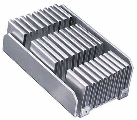 |
Figure 4. Lightweight folded fin heat sink offers high density cooling surface area.
Folded Fin
Folded fins were originally developed for the military and aerospace market to provide large amounts of surface area with very little weight. This method of making cooling surface area using corrugated metal sheet has been adopted by the commercial cooling market and is now used in every application from personal computers to radio transmitters (Figure 4). Bonded, brazed or soldered to heat spreading surfaces, these folded lengths of metal come in many styles and sizes. Manufacturing capability offers fin heights up to 4.0 inches with densities of 8 to 10 fins per inch of width. Flat fins are the most common style.
Castings
Castings are commonly used as low cost heat sinks integrated into enclosures. Due to cost, castings are limited to high volume production programs that use tens of thousands of parts. Castings typically provide near net-shaped parts that require little or no machining prior to assembly. Traditionally, the thermal conductivity of aluminum casting alloys has been significantly lower than extruded alloys. This, coupled with the potential for air pockets and inclusions in some casting styles, can yield poor thermal designs. [6]
Newly developed aluminum casting materials offer conductivities as high as 170 W/m-K. These materials offer conductivity close to extruded aluminum but still are limited by fin height to spacing ratios noted here. Also, die life using this new cast material is reduced to 1/3 of normal.
Most cast fin sections are limited in height and density to an aspect ratio of ~4:1. This limits heat dissipation levels or requires additional surfaces be added to the casting; i.e., bonded fin or folded fins.
Future Developments
Leading-edge alternatives in air-cooled heat removal are increasing. Sintered heat sinks, metal injection molding, 5X performance fans, aluminum extrusions @ 25:1 ratio and self-fanning piezoelectric fin heat sinks are visions that have not yet come to market. Many companies are working to develop these next generation products.
Improving Thermal Conductivity
Thermal conduction comes into play in two areas, heat spreading in the base, and fin efficiency. Conduction is the transfer of heat within a material due to intimate contact between molecules.
Pure aluminum has a conductivity of 230 W/m-K. Aluminum’s ability to conduct heat in thin sections is not sufficient to cool many of today’s high heat flux components.
To overcome this conduction limitation many alternative materials and techniques are being explored. These include:
- Pure copper as a base material
- Heat pipes and thermosiphons
- Increased conductivity of heat spreaders
- Copper or carbon based materials
- Vapor chambers
Each of these materials or systems will increase heat conduction compared to an aluminum extrusion. However, they will all be more costly and maybe heavier than aluminum.
Copper
At 390 W/m-K copper offers a 70% increase in conduction over aluminum. That’s the good news. The down side of copper is that it weighs three times more than aluminum, costs the same on a per pound basis and is more difficult to machine. Due to limited high temperature formability, a copper extrusion will not yield the same detail as aluminum. Also, machining copper takes more time and wears cutters at a much higher rate. However, when an application is limited in conduction, copper is a commonly used alternative.
Heat Pipes
A heat pipe is a closed-loop, phase-change heat transfer system that, by itself, does not dissipate heat. It does move heat from one point to another with a very low temperature rise. An average heat pipe has an equivalent thermal conductivity of up to 1000 W/m-K. Although it is not strictly correct to quote thermal conductivity of a heat pipe, it is used here as a comparison to solid materials.
The heat transport mechanism of a heat pipe is latent heat transport via vapor flow and not thermal conduction. When a value of thermal conductivity is given for a heat pipe, it is usually the equivalent thermal conductivity that a solid conductor of the same cross-sectional area and length would require to conduct the same amount of heat from end-to-end with the same temperature rise. The addition of heat pipes to an aluminum heat spreader can improve the conductivity and reduce spreading resistance with a minimum of weight increase (Figure 5).
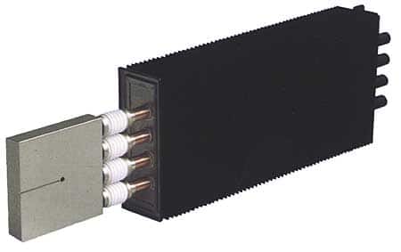 |
Figure 5. Example of an electrically isolated heat pipe assembly.Heat pipes come in various sizes and styles, typically round but also in square or rectangular cross sections. Most heat pipes used in electronic cooling are copper with water or alcohol as the working fluid. Heat pipes with sintered wicks are the current state of the art and provide the highest heat flux density control. They also are best at returning liquid against gravity by capillary flow.
Thermosiphons use buoyancy effects caused by a temperature difference in the working fluid to move heat inside a closed system. These systems can be either single phase (liquid only) or two phase (evaporative and condensing).
Loop heat pipes are similar to conventional heat pipes in that they use a phase change liquid to move heat. They are different in that the system forms a circulating loop with hot vapor and cooled liquid in separate lines to and from the condenser. [7]
Vapor Chambers
Vapor chambers, or flat plate heat pipes, are currently receiving a lot of attention. These parts also use a change of phase liquid to move heat. The vapor chamber provides a uniform temperature across the heat dissipation surface with low mass. This technology allows direct attachment of heat dissipation fins and can be used for air-cooling of applications including microprocessors, RF frequency transmitters, thermoelectric devices and power modules.
Advances in vapor chamber technology will revolve around improved wick structures and working fluids. However, water still appears to have the best characteristics for moving heat.
Improved Conductivity Materials
High thermal conductivity polymers, carbon-based composites, sintered metallic powders, phase-change compounds, synthetic diamonds and strand-oriented graphite materials are all part of leading edge thermal conductivity materials. What are the most desirable properties? These are controlled levels of conductivity, high machinability, low weight, low coefficient of thermal expansion, low toxicity and above all a per pound cost that will be lower than aluminum. Can this be done? So far it hasn’t happened. Many new materials do offer better physical properties than aluminum, but the cost is many times higher.
Aluminum Silicon Carbide
AlSiC stands out as one of the most promising new materials. Mixed with various aluminum alloys it can be tailored to specific physical properties. Controlled thermal expansion, high conductivity and significant strength make AlSiC attractive. Due to cost, this material is typically used in base sections and as substrates for direct die attachment in power module bases. Some applications use this material to form the entire heat sink although due to cost an aluminum extrusion is typically used.
Table 1 offers a comparison of various heat sink materials.
|
Table 1. Comparison of Various Heat Sink Materials
Liquid-Cooling
Liquid-cooling, typically a water and glycol mixture, overcomes most of the heat removal and transport limitations of air-cooled systems. Smaller heat sink volumes, elimination of audible noise, the ability to move rejected heat away easily from the user area, and significantly increased system reliability are all liquid-cooling characteristics (Figure 6). The problem is that only a few markets currently accept liquid-cooled electronics.
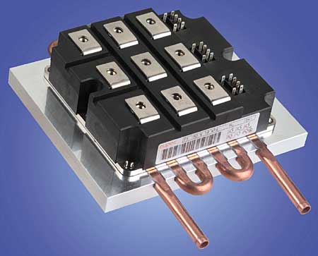 |
Figure 6. Liquid cooled heat sinks reduce volume over air-cooled parts.The primary resistance is customer acceptance. The concept of a liquid-cooled personal computer has yet to gain general market acceptance. However, as heat fluxes exceed 100 Watts per square inch, the need for phase change heat transfer or liquid cooling are the only alternatives.
System Solutions – Start with Thermal in Mind
Over the last few decades heat dissipation has become an increasing problem for electronics designers. Today the thermal engineer needs to be an integral part of the design team and not an afterthought. Typically the electronic designs are done and PC boards complete before heat sinks are considered. Thermal performance can limit a product’s marketability due to the amount of power output and the features that can be incorporated.
To ensure reduced time to market and success, heat dissipation must be one of the top design considerations. If engineering teams design with thermal considerations in mind, the resulting systems will be quieter, smaller and less expensive. To do this, every level of a company’s management must be aware of the importance of including the thermal engineer in the design concept team.
The following precepts are key to success:
- The initial design effort must include a thermal engineer with experience enough to spot trouble sites before they are locked in.
- The increased usage of computer design programs such as Icepak, Maya and FLOTHERM will allow problems to be addressed before electrical designs are finished.
The best defense is education of electrical engineers, while they are still in college, about the nature and consequences of thermal problems and their solution sets.
References
1. “What Does the Future of Thermal Management Hold for Electronics?” – http://www.me.umn.edu/divisions/tht/tme/tme4.html
2. Jordan, W.D., “A Conceptual Design Discussion of Technical Thoughts/Ideas Supporting Powergain Technology”, PCIM Show, Las Vegas, September, 1996.
3. Soule, Christopher A.,”Augmented Fin Air-Cooled Heat Sinks Achieve Higher Performance without Significant Rise in Static Pressure”, PCIM Magazine, November, 1997, Pages 16-21.
4.Fleischer, Amy, “Jet Impingement Cooling – Background”, University of Minnesota, http://www.me.umn.edu/~amyfleis/background.html
5. Soule, Christopher A., “Forced Air Boundary Layer Thickness and Serrated Fin Heat Sinks”, PCIM Magazine, August, 1977, Pages 104-111.
6. Keller, Kurtis, “Cast Heat Sink Design Advantages”, Dept. of Computer Science, UNC Chapel Hill, NC, http://www.cs.unc.edu/~keller/Papers/Itherm98/Itherm
7. Los Alamos Heat Pipe Home Page – http://www.lanl.gov/orgs/esa/epe/Heat_Pipe_Site/Ht_Pipe_top.html


